
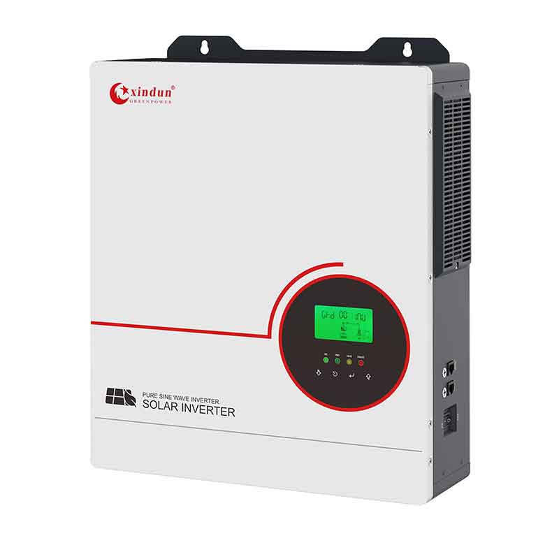
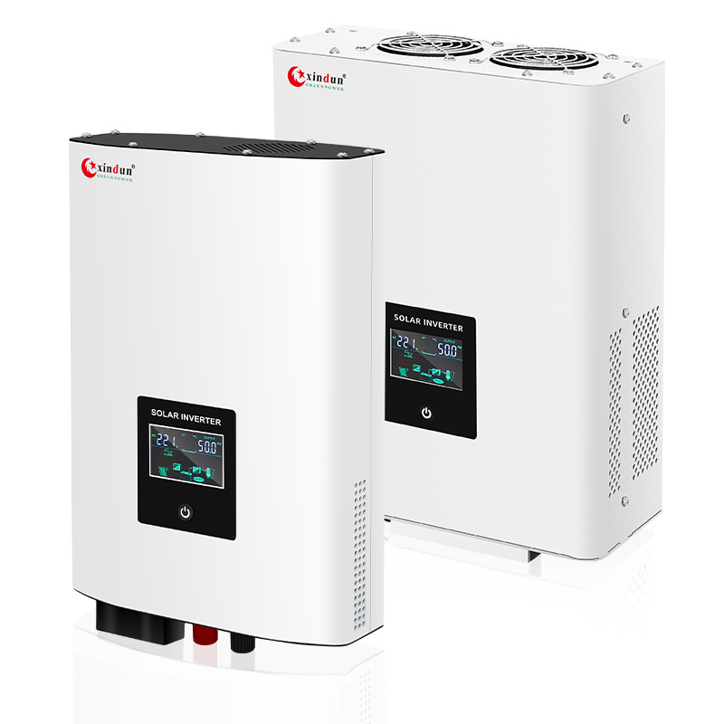
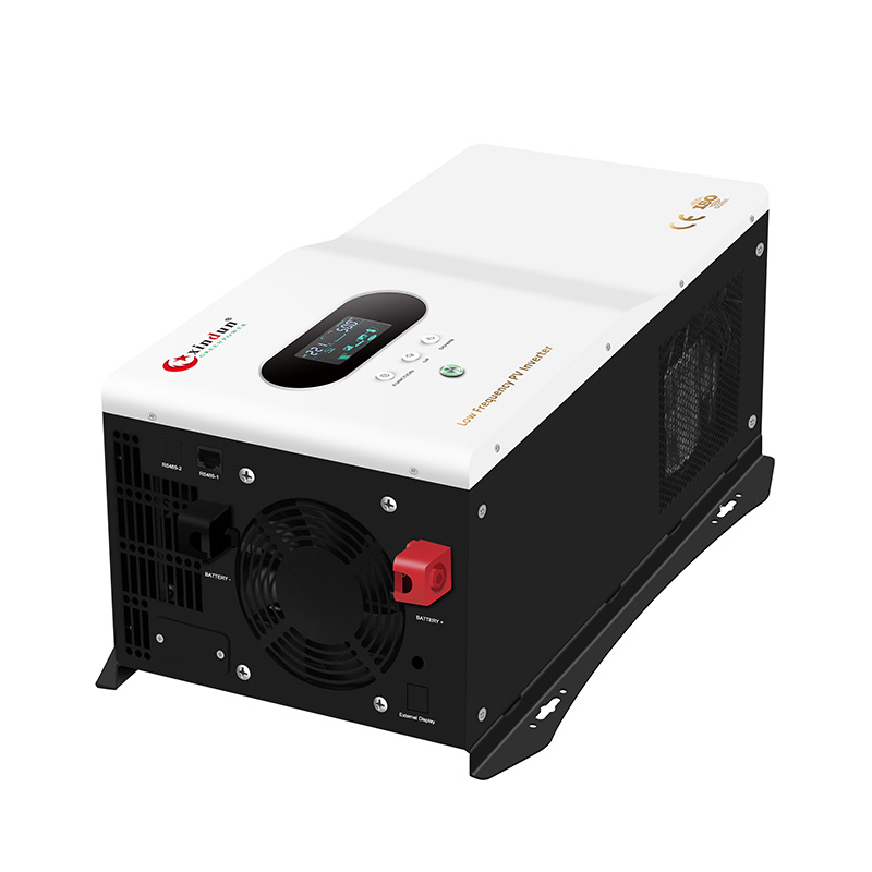
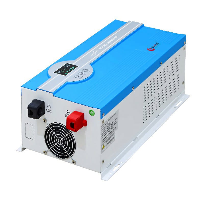
 Solar Inverter
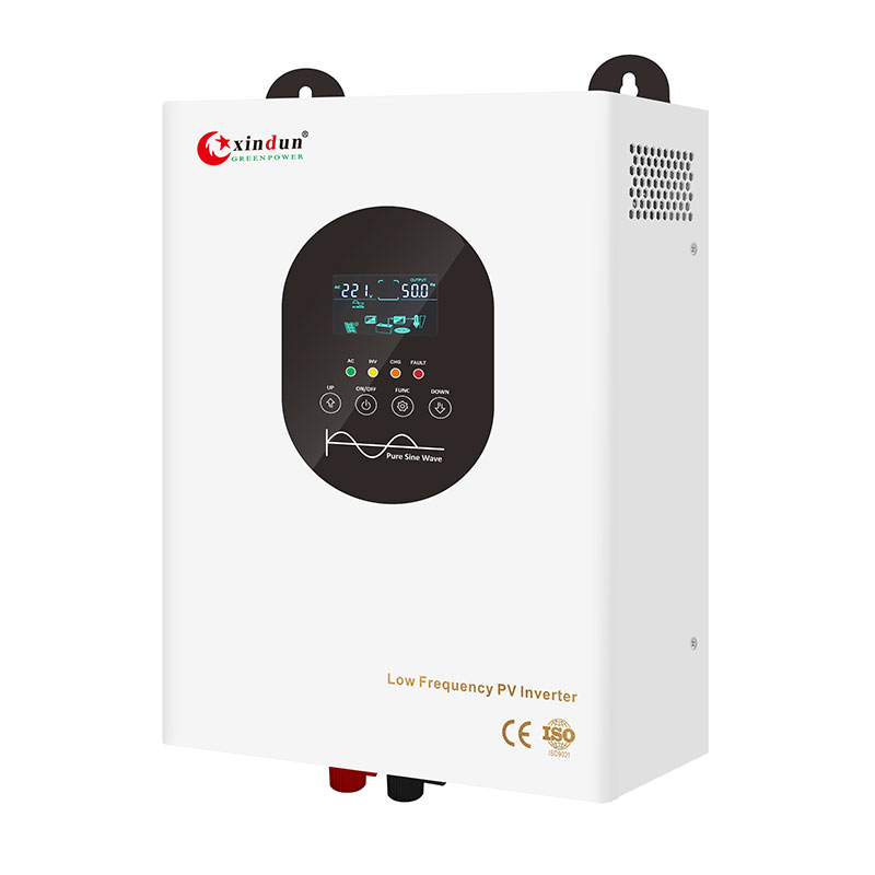
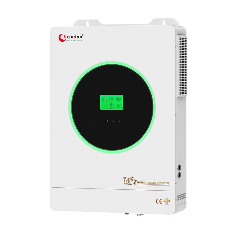
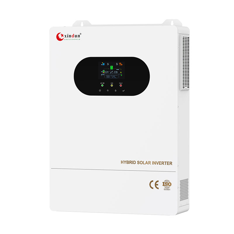
 Hybrid Inverter
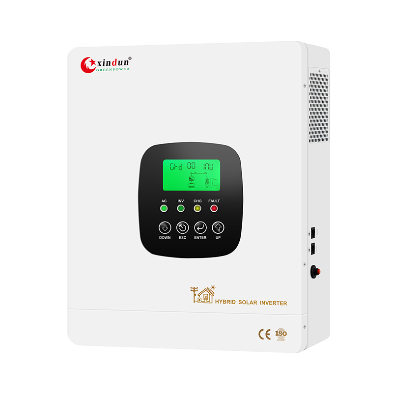
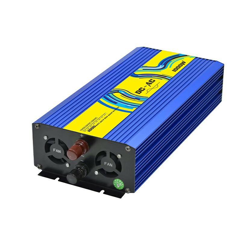
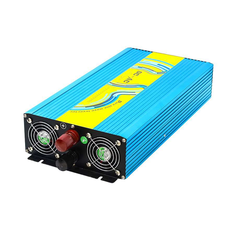
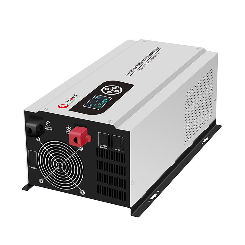
 Power Inverter
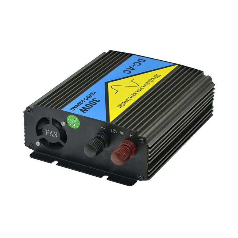
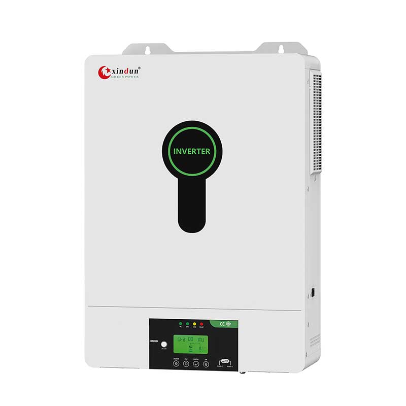
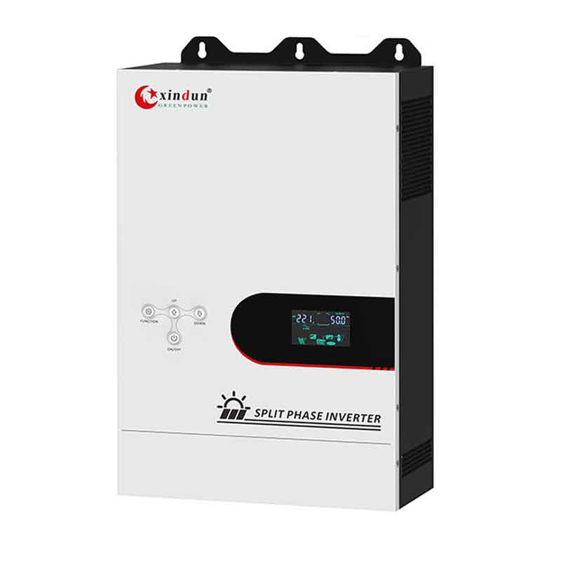
 Split Phase Inverter
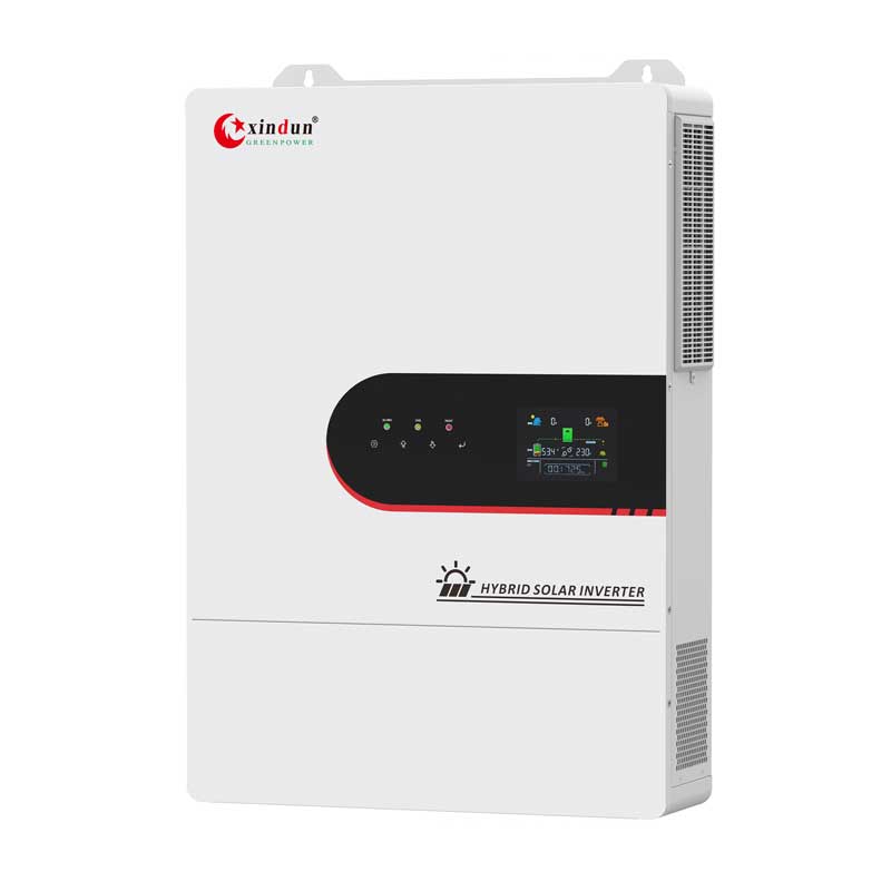
 Energy Storage Inverter
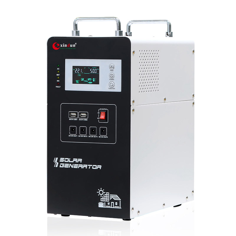

 3 Phase Inverter
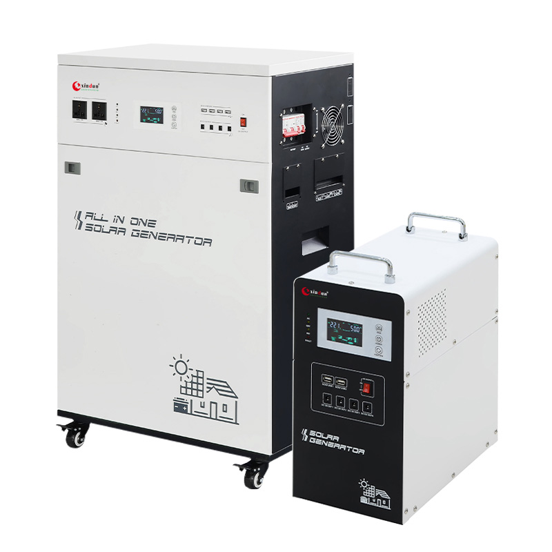
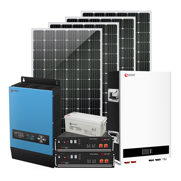
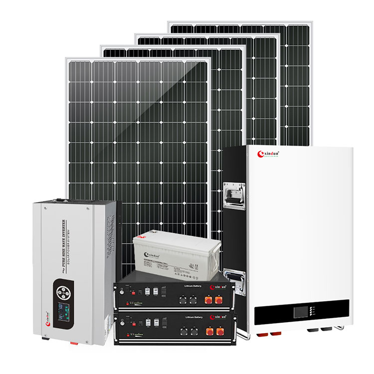
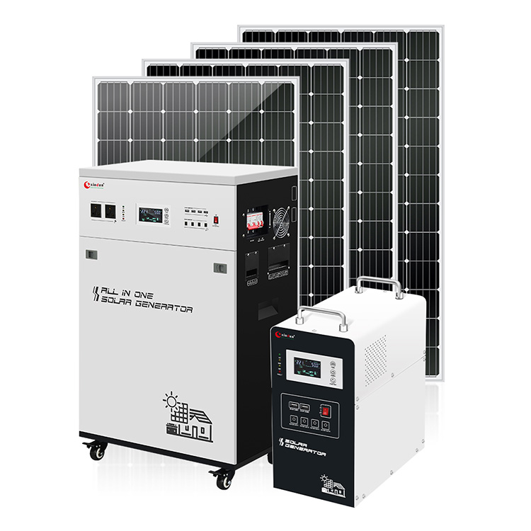
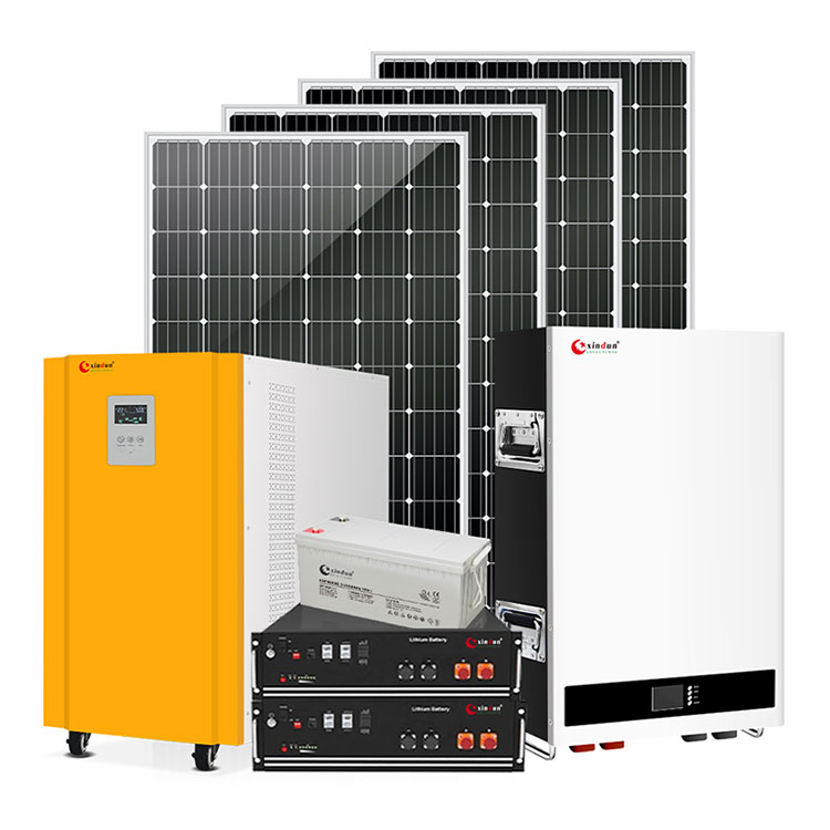
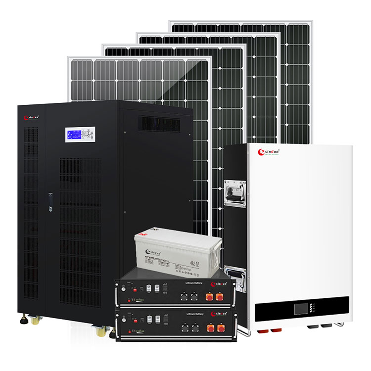
 Solar System Kits
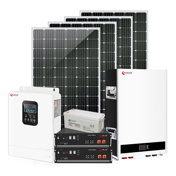
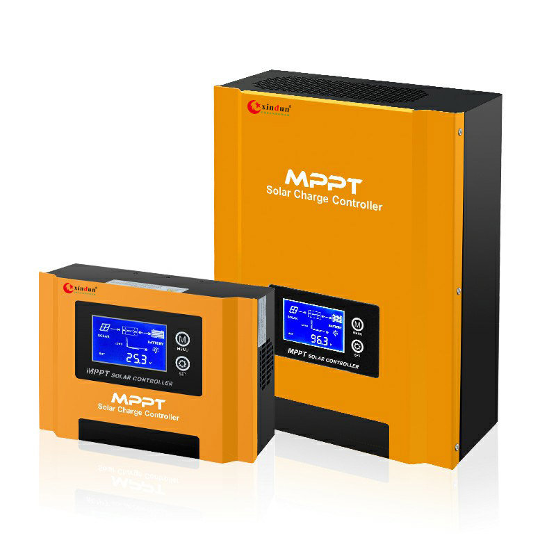
 Solar Charge Controller
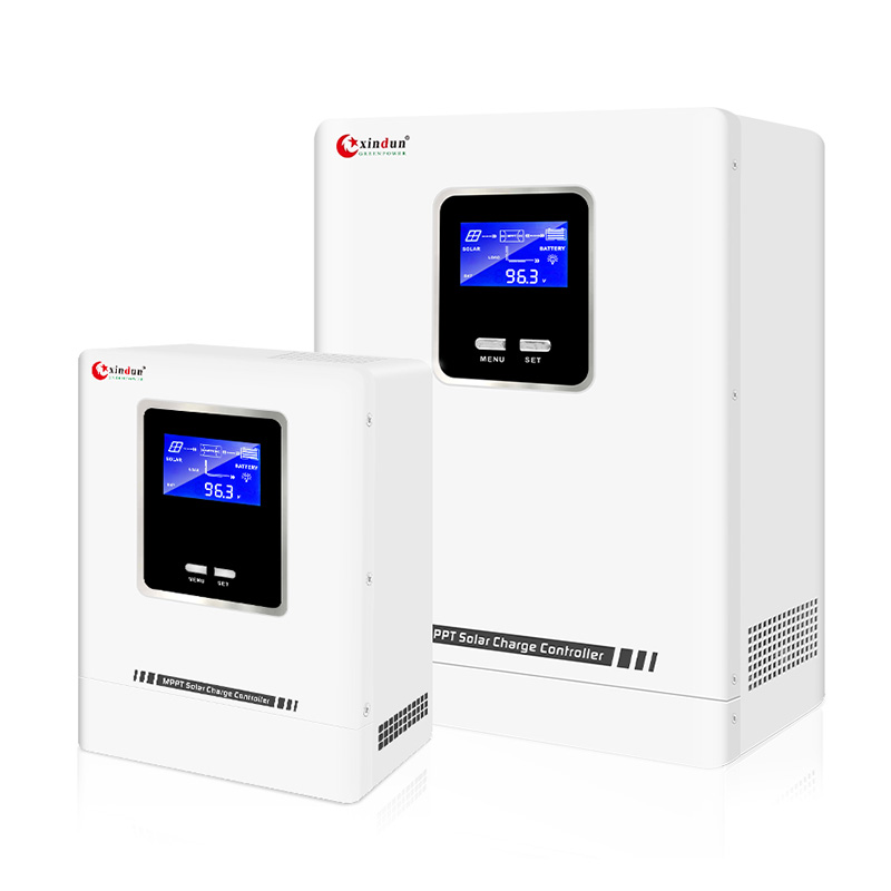

 Solar Battery
 Asia
Asia
 Africa


 South America
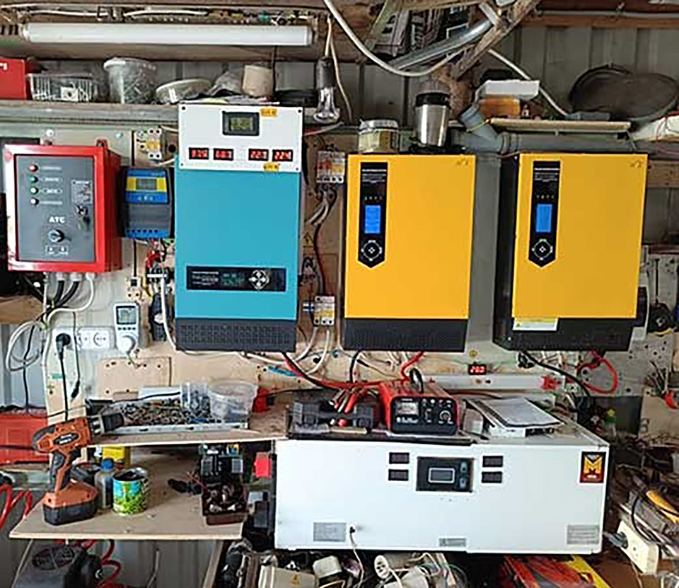
 Europe
 North America

 Oceania & Antarctica


 Home
HomeHow Many Parallel Output Modes Does Xindun Split Phase Solar Inverter Have?
 Dec 26,2025

 XINDUN
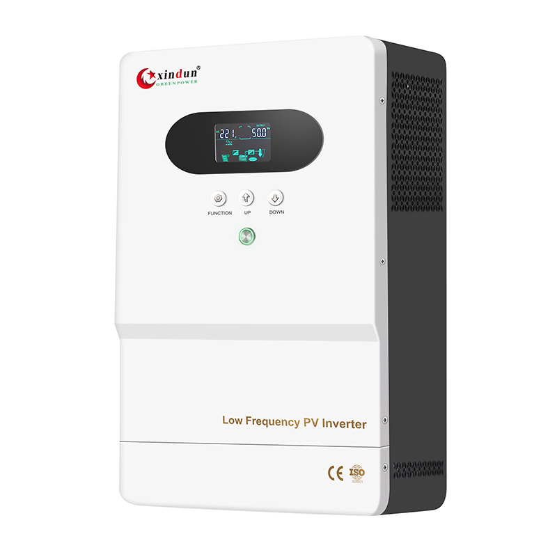
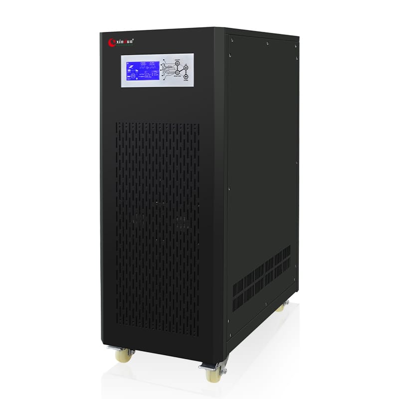
The Xindun HU series high frequency split phase solar inverter supports split phase input and split phase output. Split phase solar inverter is a device that converts direct current (DC) to alternating current (AC) and splits the output voltage. Through internal circuit design, it converts the input DC power into two AC outputs with 180 degree phase difference, thus meeting the power requirements of specific scenarios. This technology is commonly used in environments requiring balanced loads or special voltage configurations, such as US standard residential or commercial power system.
The Xindun HU series high frequency split phase solar inverter is inverter designed with high frequency pure sine wave, enabling efficient inverter conversion output. This inverter supports multiple operating modes, including hybrid, off grid, and on grid. Notably, it meets US standard grid voltage requirements, making it US standard split phase inverter that satisfies the stringent standards for power equipment in the Latin American market.
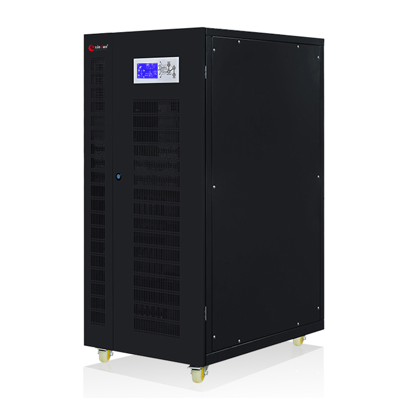
HU series split phase solar inverter offers both single phase and split phase operating modes and supports up to six inverters operating in parallel, thereby increasing the system's total output power and fully meeting the user's future system expansion needs.

HU series split phase solar inverter not only provides stable power support but also allows for flexible adjustment of the output mode according to user needs. It can achieve different parallel output modes through inverter paralleling to adapt to different power consumption scenarios and load demands. This flexibility makes the split phase solar inverter widely applicable in residential and commercial power systems. Users can further optimize equipment performance through reasonable parameter settings to ensure the stability and efficiency of power supply.
So, what are the different parallel output modes of the HU series split phase solar inverter?
The HU series split phase solar inverter can be used in parallel output in both single phase and split phase operation modes, offering four parallel output modes: single phase parallel output, 2 phase split phase parallel output, split phase parallel output, and three phase parallel output.
In single phase parallel output mode, it can provide higher total output power, suitable for single phase power applications such as homes and small shops. 2 phase split phase parallel output achieves more balanced power supply by distributing the load across two phases; this mode is often used in environments requiring balanced loads. The split phase parallel output mode fully utilizes the characteristics of split phase technology, meeting the needs of special voltage configurations, and is suitable for US standard system in residential or commercial power applications. The three phase parallel output mode further expands the application range of the equipment, enabling it to adapt to more diverse power demands, especially performing exceptionally well in industrial or large commercial systems.
The flexibility and versatility of these parallel output modes enable HU series split phase inverters to precisely match specific power demands in practical applications. Whether facing the stability requirements of residential power supply or the complex load conditions in commercial and industrial scenarios, these modes provide reliable power support. Furthermore, users can flexibly select and adjust the parallel output mode according to the actual on site configuration and future expansion plans, thereby maximizing resource utilization. This design not only enhances the adaptability of the equipment but also brings users greater economic benefits and ease of use.
How to set the single phase parallel output mode of the HU series split phase inverter?

During single phase parallel operation, each inverter needs to be connected to the parallel communication line. Users need to uniformly set the relevant parameters of the HU series split phase solar inverter.
First, select the "PAL" option in the "Parallel Mode" parameters to enable the inverter parallel function.
Next, set it to "Single phase mode" under "AC Phase Mode".
Then, set the "AC Output Voltage" option, for example, selecting "120V" AC voltage. There are four AC output voltage values available: 100V, 105V, 110V, and 120VAC.
The above three parameters must be set consistently for each inverter. For detailed parameter settings for inverter parallel operation, please refer to the HU series split phase solar inverter manual.
The core function of single phase parallel operation is to increase the total power output of the system, with same phase, power superposition, and constant voltage. When the power of single inverter is insufficient to power all loads, inverters are connected in parallel to provide greater power output. The system output voltage remains single phase (only L and N, e.g., 120V), without changing the system's voltage phase structure.
It's important to note that while single phase parallel operation significantly increases the system's total power output, it also increases the demand on battery capacity. Therefore, when connecting inverters in parallel, users should configure the battery capacity appropriately based on the actual load power and operating time requirements to avoid system interruptions due to insufficient power.
The HU series split phase solar inverter is a versatile solar inverter. It not only achieves split phase dual voltage output but also switches between hybrid, off grid, and on grid modes, and supports battery-free operation (single unit mode). Furthermore, this inverter features time segmented charging and discharging settings, providing three customizable time periods for charging or discharging, rationally allocating mains power, solar , and battery power.
How is the split phase parallel output mode of the HU series split phase solar inverter set? During the split phase parallel operation, each inverter needs to be connected to the parallel communication line, and then the relevant parameters of the HU series split phase solar inverter must be configured uniformly.
First, select the "PAL" option in the "Parallel Mode" parameters;
Second, set the "AC Phase Mode" to "180" (i.e., split phase mode);
Next, set the "AC Output Voltage" option, for example, selecting an AC voltage value of "120V".
After completing the split phase parallel setup, the phase voltage output of all inverters between the live wire and neutral wire (L-N) is 120V, while the line voltage output between the two live wires (L1-L2) becomes 240V.
Even if only one inverter is paralleled, the output voltage is split phase dual voltage. The split phase parallel system has excellent load balancing capabilities, making it ideal for scenarios requiring simultaneous power supply or expansion of systems using both 120V and 240V voltages, such as residential and commercial applications in North America. These applications utilize high power appliances conforming to US standard and small industrial split phase equipment (split-phase air conditioning units, 240V high power production tools, etc.). When these devices require split phase 240V power and the power of a single inverter is insufficient, split phase parallel operation can provide the corresponding voltage and increase the total power, ensuring stable operation of the equipment.
How to set the split phase parallel output mode of the HU series split phase inverter?

During the split phase parallel operation, each inverter needs to be connected to the parallel communication line, and then the relevant parameters of the HU series split phase inverter must be configured uniformly.
First, select the "PAL" option in the "Parallel Mode" parameters;
Second, set the "AC Phase Mode" to "180" (i.e., split phase mode);
Next, set the "AC Output Voltage" option, for example, selecting an AC voltage value of "120V".
After completing the split phase parallel operation settings, the phase voltage output of all inverters between the live wire and neutral wire (L-N) is 120V, while the line voltage output between the two live wires (L1-L2) becomes 240V.
Even if only one inverter is paralleled, the output voltage is split phase dual voltage. The split phase parallel system has excellent load balancing capabilities, making it ideal for scenarios requiring simultaneous power supply or expansion of systems using both 120V and 240V voltages, such as residential and commercial applications in South America. These applications utilize high power appliances conforming to US standards and small industrial split phase equipment (split phase air conditioning units, 240V high power production tools, etc.). When these devices require split phase 240V power and the power of a single inverter is insufficient, split phase parallel operation can provide the corresponding voltage and increase the total power, ensuring stable operation of the equipment.
How to set the 2 phase parallel output mode of the HU series split phase inverter?

Unlike single phase and split phase parallel operation, 2 phase parallel operation requires dividing multiple inverters into two groups: one group "P1" and the other "P2". These two groups are combined in different quantities to create 2 phase parallel system. For parallel combinations of 3 or more inverters, there are 7 different combinations. The output voltages of the two groups will have a specific phase difference (120 degrees and 180 degrees respectively). After conversion by the inverter, a 2 phase voltage is finally formed to provide power to loads requiring 2 phase electricity.
The 2 phase parallel inverter system has the following different combinations:
2 inverters in parallel: 1 combination. "1+1" combination: 1 inverter in group "P1" and 1 inverter in group "P2".
3 inverters in parallel: 1 combination. A "2+1" configuration: 2 inverters are assigned to group "P1", and 1 to group "P2", or vice versa (1 inverter to group "P1" + 2 to group "P2").
A parallel operation of 4 inverters has two configurations:
Configuration 1: "3+1" configuration: 3 inverters to group "P1", 1 to group "P2".
Configuration 2: "2+2" configuration: 2 inverters to group "P1", 2 to group "P2".
A parallel operation of 5 inverters has two configurations:
Configuration 1: "4+1" configuration: 4 inverters to group "P1", 1 to group "P2".
Configuration 2: "3+2" configuration: 3 inverters to group "P1", 2 to group "P2".
A parallel operation of 6 inverters has three configurations:
Configuration 1: "5+1" configuration: 4 inverters to group "P1", 1 to group "P2".
Combination 2: "4+2", 3 units assigned to group "P1", 3 units assigned to group "P2".
Combination 2: "3+3", 3 units assigned to group "P1", 3 units assigned to group "P2".
During 2 phase parallel operation, each inverter needs to be connected to the parallel communication line. Users need to set the corresponding parameters in each group of HU series split phase solar inverter.
First, all inverters in group "P1" should select the "2P0" option under the "Parallel Mode" parameter (there are three options: "2P0", "2P1", and "2P2").
Second, all inverters in group "P2" need to select either "2P1" or "2P2". "2P1" indicates 120 degree phase difference between the two voltage groups, with an output line voltage of 208V; "2P2" indicates a 180-degree phase difference between the two voltage groups, with an output line voltage of 240V.
Then, in "AC Phase Mode," it must be set to "0" (single phase mode) and cannot be changed.
Finally, you also need to set the "AC Output Voltage" option, selecting a "120V" AC voltage value.
The core of 2 phase split phase parallel operation is its adjustable phase difference. Users can choose two different dual voltage outputs based on their actual usage scenarios:
A: AC120V and 208V dual voltage, 120-degree phase difference – L1-N: 120V, L2-N: 120V; L1-L2: 208V
B: AC120V and 240V dual voltage, 180 degree phase difference – L1-N: 120V, L2-N: 120V; L1-L2: 240V
The line voltage with 120 degree phase difference is 240V, and the line voltage with 180 degree phase difference is also 240V. This is the same as the voltage output of split phase parallel operation, offering flexible output voltage. This specific 208V voltage is commonly found in 2 phase three phase systems in North America. Therefore, in North America, the 2 phase split phase parallel output voltage of the HU series split phase solar inverter is well compatible with local grid standards, meeting the stringent output voltage requirements of specific equipment.
How to set the three phase parallel output mode of the HU series split phase solar inverter?

Similar to 2 phase parallel operation, three phase parallel operation also divides multiple inverters into three groups: "P1", "P2", and "P3". These three groups of inverters are combined in different quantities to form three phase parallel system. It's important to note that at least three inverters are required to form complete three phase system.
The three phase parallel inverter system has the following different combinations:
3 inverters in parallel, one combination: "1+1+1" combination, one inverter in group "P1", one in group "P2", and one in group "P3". This is the most basic three phase parallel combination; a minimum of 3 inverters are required to form three phase parallel system.
4 inverters in parallel, one combination. A "2+1" combination: 2 inverters are assigned to group "P1", and 1 to group "P2", or vice versa (1 inverter to group "P1" + 2 to group "P2").
A parallel operation of 4 inverters has one combination: a "2+1+1" combination, with 2 inverters assigned to group "P1", 1 to group "P2", and 1 to group "P3".
A parallel operation of 5 inverters has two combinations:
Combination 1: A "3+1+1" combination, with 3 inverters assigned to group "P1", 1 to group "P2", and 1 to group "P3".
Combination 2: A "2+2+1" combination, with 3 inverters assigned to group "P1", 2 to group "P2", 1 to group "P2", and 1 to group "P3".
Six inverters can be operated in parallel, with two possible combinations:
Combination 1: A "2+2+2" combination, with 2 inverters assigned to group "P1", 2 to group "P2", and 2 to group "P3".
Combination 2: A "3+2+1" combination, with 3 inverters assigned to group "P1", 2 to group "P2", and 1 to group "P3".
In practical applications, different combinations can meet diverse power demands and scenario requirements.
During three phase parallel operation, each inverter needs to be connected to the parallel communication line. Users need to set the corresponding parameters in each group of HU series split phase solar inverter.
First, set all inverters in group "P1" to the "3P1" option under the "Parallel Mode" parameter (there are three options: "3P1/3P2/3P3").
Second, select "3P2" for all inverters in group "P2", and select "3P3" for all inverters in group "P3".
Next, set the "AC Phase Mode" to "0" (single phase mode). This setting cannot be changed to ensure 120 degree phase difference in voltage between each group.
Finally, each inverter in each group needs to have its "AC Output Voltage" option set to "120V" AC voltage.
The final output is three phase voltage, with phase voltages (L-N) at 120V and line voltages (L1-L2/L1-L3/L2-L3) at 208V, conforming to US standard three phase power supply standards.
The core of three phase parallel operation is 120 degree phase difference, standard three phase four wire system, and the requirement of at least three inverters to form three phase system. Three phase parallel output is suitable for industrial and commercial equipment and scenarios requiring three phase power supply. Different inverter three-phase parallel combinations can meet different user needs and application scenarios.
Should the battery connected to the inverter parallel system be connected in parallel or in series?
We previously introduced the different parallel output modes of the HU series high frequency split phase solar inverter. And how are various parallel output modes set? When connecting battery banks to inverter parallel system, are the battery connected in parallel or series? Inverters can increase the system's power output by operating in parallel.
In inverter parallel system, batteries are connected in parallel, not series. Regardless of whether the battery banks are connected in series or parallel, the battery voltage must match the inverter's parameters for operation. This is the fundamental reason. Each inverter in parallel system has uniform DC input battery voltage parameter; the rated battery voltage will not increase due to inverter parallel operation.
Taking the Xindun HP PLUS+ hybrid inverter parallel model as example, this inverter's rated battery voltage parameter is 48VDC. If the battery banks are connected in series, the total voltage will be the voltage of single battery bank multiplied by the number of banks connected in series. For example, connecting two 48V batteries in series will result in voltage of 96V. The 96V battery voltage far exceeds the rated DC input voltage of single inverter battery (48V, battery voltage range 42-60V), exceeding the equipment's voltage range. This can damage internal components such as capacitors, causing the inverter to burn out, and in severe cases, even leading to a fire. Therefore, the battery voltage of the battery pack must be matched to the rated DC input voltage of each inverter to prevent overvoltage damage.
The core requirement of inverter parallel operation is to increase the total system power without changing the voltage. Therefore, the batteries are connected in parallel to maintain voltage matching with the inverter's rated voltage. Parallel connection ensures consistent voltage across each battery pack, avoiding the risk of system failure due to single battery malfunction. Parallel connection also allows for easy increase of battery pack capacity to meet higher energy storage demands, better balanced management among battery packs, extended overall battery life, improved system efficiency and stability, and easier maintenance, reducing operating costs. These design considerations are all for system safety, reliability, controllability, and scalability.
It is important to note that batteries connected in parallel must be of the same brand and have the same specifications, including battery type, rated voltage, capacity, and condition (newness or age). This avoids uneven charging and discharging due to differences in battery performance, which can affect the overall lifespan of the battery pack and the stability of the system. Simultaneously, ensure that the wiring is secure and the positive and negative terminals are correct during connection to prevent short circuits or poor contact, ensuring safe and reliable system operation.
If you would like to learn more about Xindun inverter parallel operation, you can leave your information and requirements in the customer service window at the bottom of the website (https://www.xinduninverter.com/). Xindun will contact you as soon as possible during working hours.
 What is the Time of Use Charging and Discharging Function of Parallel Hybrid Inverter?
 Top Selling Products